Slip Clutches
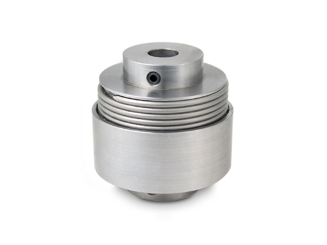
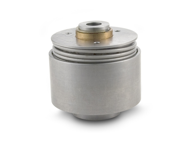
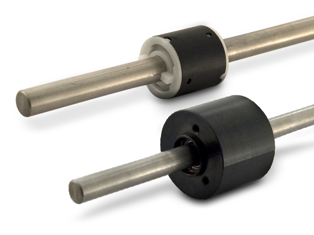
The basic function of a slip clutch is to control torque between two components. SDP/SI carries a variety of mechanical slip clutches, including standard and precision slip clutch assemblies, spring-wrapped slip clutches, and inline mechanical slip clutches. Click here to download our clutch application diagram.
Clutch Applications & Features
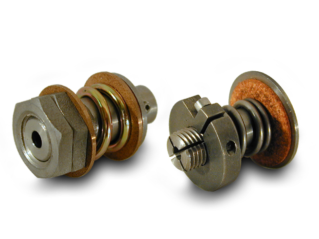
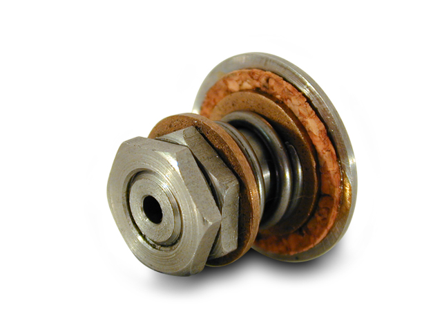
Fully adjustable, intermittent-duty slip clutch assemblies are available from SDP/SI. These assemblies function as a buffer against temporary overload between a shaft and a mounted component (gear or pulley).
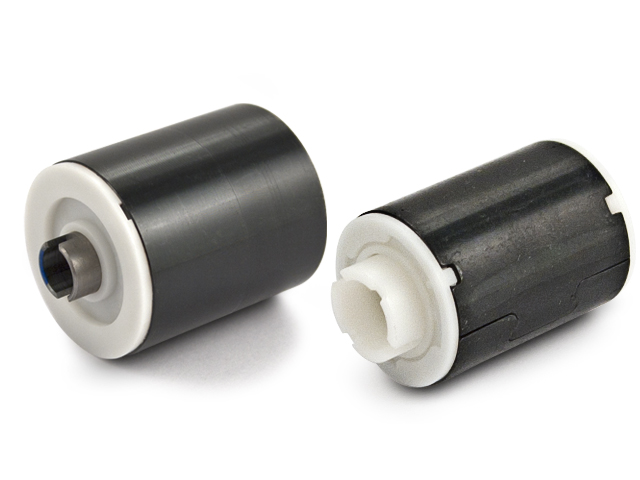
Our mechanical spring-wrapped (continuous) slip clutches are made to accept gears, sprockets, or pulleys. Regardless of the direction of rotation, slip torque is constant and velocity independent. Applications for the spring-wrapped clutches include tension control of film or tape drives and transmission overload protection.
They feature:
- Long life under continuous slip conditions
- Unidirectional or bidirectional operation
- Same or different clockwise and counterclockwise torques.
- Precise and stable limit torque calibration (range: 0.007 to 4.24 N • m)
- Same torque at breakaway as at high slip velocities
- Corrosion-resistant materials
The slip coupling serves as a torque limiter as well as a coupling for two colinear shafts. This coupling is equipped with hubs at both ends for pinning to the (two) shafts. When the load exceeds the limit torque of a slip coupling, the two shafts rotate relative to each other at the full limit torque. The standard coupling is designed to operate with 3° angular or linear misalignments of up to 0.25 mm between the two shafts. The mounting hole diameters of the slip couplings can differ for the two ends, so that different diameters of “in-line” shafts can be coupled together.
Inline multiplate slip clutches regulate torque for three types of slip:

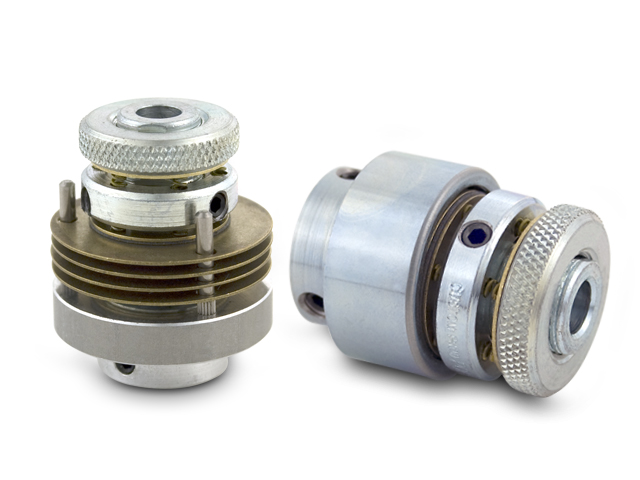
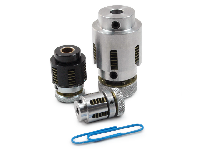
The cartridge and a housing make up the clutch assemblies (see cutaway above). The cartridge is made up of the hub, adjustment nut, detent plate (washer), springs, collar, inner & outer plates, and friction pads. The housing contains the torque pins which engage the outer plates of the cartridge.
The cartridge is set-screwed or keyed to the input shaft and the housing can also be set-screwed or keyed to the output shaft. In the example above, it is attached to the output pulley or gear, with a bronze bearing to allow relative motion between the input shaft and the output pulley (or gear).
The hub's flats transfer torque to the mating flats on the inner plates; the outer plates' friction pads transfer torque to the outer plates and the torque pins transfer torque to the housing and the output pulley (or gear). Compressing the springs by turning the adjustment nut will allow the torque level to be adjusted and controlled. The clutch engages when the controlled torque level exceeds the low torque. When the applied torque is more than the intended (set) torque, the clutch slips.
When using a fixed torque clutch, a collar is fastened to the hub in a fixed position, The housing or the input shaft can act as the input portion during operation, with the other portion being driven.


